



-

Micro LSR Seal Design: Flash Prevention Tips for Precision Molding
-
Advantages of Liquid Silicone Rubber (LSR): Why It Is Replacing Traditional Rubber and Plastics
-
LSR Injection Molding (Cold Runner) vs. Compression Molding LSR (Runnerless): Process & Selection Guide
-
Medical Injection Molding DFM Checklist & Design Guidelines

Micro LSR Seal Design: Flash Prevention Tips for Precision Molding
2026-10-23


复制成功
Micro liquid silicone rubber (LSR) seals play a critical role in medical devices, wearable electronics, miniature connectors, automotive sensors, and other precision-engineered products. However, as sealing components become smaller, even a thin layer of excess silicone along the parting line can affect dimensional accuracy, sealing performance, assembly, and product appearance.
For engineers developing a micro LSR seal design, flash prevention is not simply a matter of adjusting injection parameters. It requires coordinated control of part geometry, mold parting lines, cavity precision, venting, clamping force, material behavior, and production conditions.
In liquid silicone rubber injection molding, small gaps between mold components can allow uncured silicone to escape, creating flash. This challenge becomes more demanding when the seal features narrow lips, thin cross-sections, miniature grooves, or tight dimensional tolerances.
This guide explains practical micro LSR seal flash prevention techniques, from early-stage product design to precision tooling and production process optimization. It also highlights common design mistakes and explains how manufacturers can reduce flash-related defects before committing to high-volume production.
1. What Causes Flash in Micro LSR Seals?
Flash is excess material that escapes from the intended cavity and solidifies along mold parting lines, inserts, vents, or other interfaces.
In micro liquid silicone rubber injection molding, flash can develop even when the excess material appears visually insignificant. The impact depends on the seal's functional surfaces, assembly method, material properties, and dimensional requirements.
1.1 Common Causes of LSR Molding Flash
Poor mold shut-off conditions
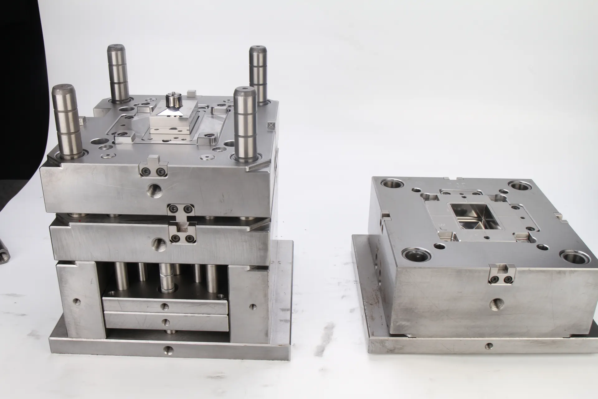
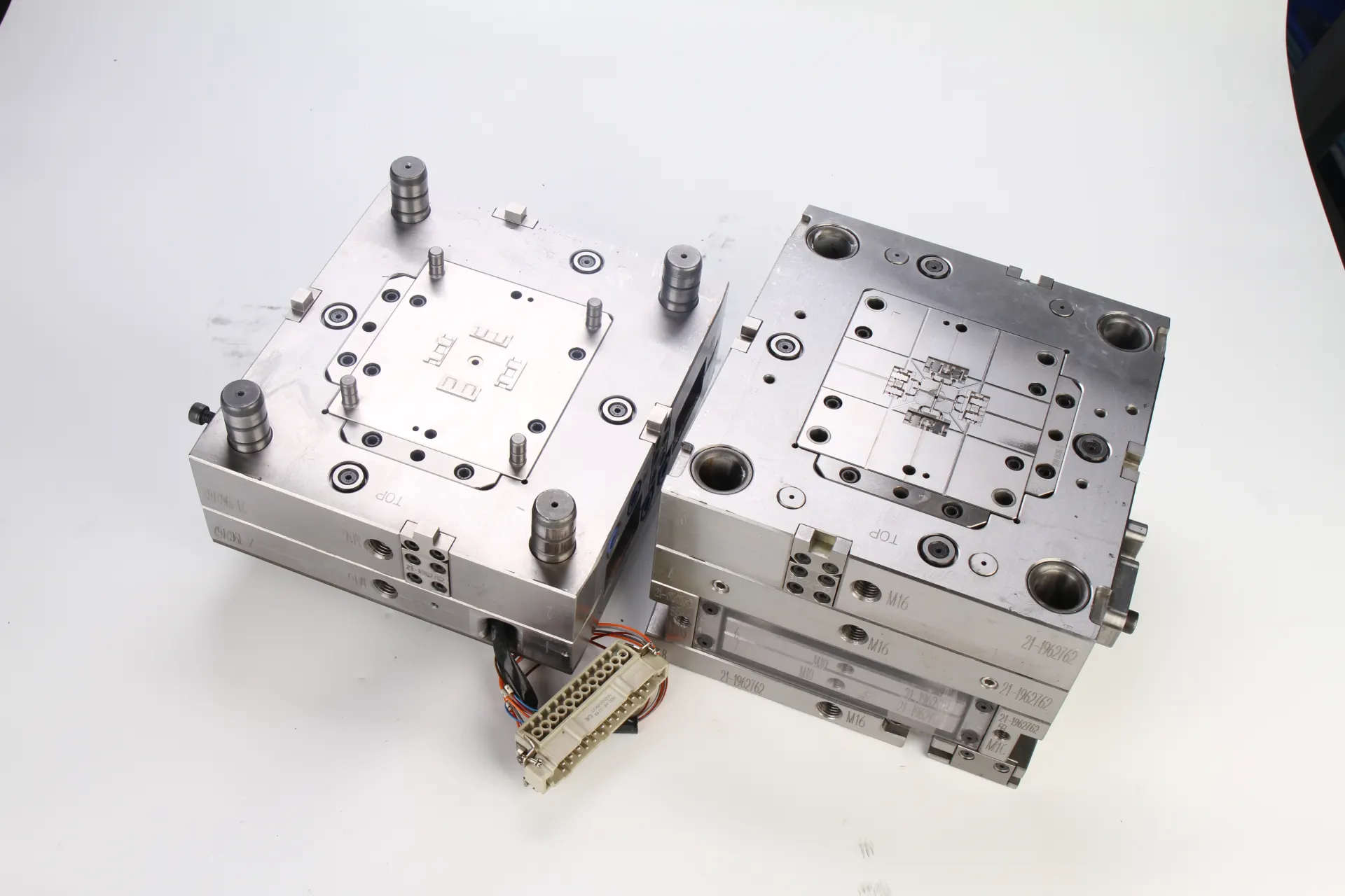
Gaps caused by machining errors, insufficient contact, wear, contamination, or mold deformation can create paths for uncured LSR to escape.
Improper parting line placement
If the parting line crosses a critical sealing lip or functional surface, even a small amount of flash may interfere with assembly or sealing performance.
Insufficient or uneven clamping
When the effective clamping force cannot resist the pressure acting on the projected cavity area, the mold may open locally. Uneven contact or structural deflection can also contribute to flash.
Unbalanced injection and filling conditions
Excessive injection pressure, unsuitable filling profiles, or poor runner and gate design may increase the risk of material entering small clearances.
Unsuitable venting design
Vents must release trapped air while restricting the flow of liquid silicone. Vents that are too deep, poorly positioned, or inadequately controlled may become flash paths.
Material and process variation
Changes in material viscosity, temperature, mixing conditions, or curing behavior can affect filling and flash formation. The actual effect depends on the LSR formulation and molding system.
Understanding the root cause is essential. Simply reducing injection pressure may conceal the symptom while creating short shots, incomplete filling, or inconsistent seal dimensions.
2. Optimize Parting Line Design
Parting line design is one of the most important factors in micro LSR seal flash prevention.
The parting line determines where the mold separates and where the molded component may develop a visible or functional witness line.
2.1 Place the Parting Line Away From Critical Sealing Surfaces
Whenever the product geometry allows, position the parting line away from the primary sealing lip, contact surface, or precision sealing diameter.
For example, a miniature circular gasket may have a thin sealing edge that must contact a mating component evenly. If the parting line crosses that edge, flash may create a local high spot and compromise contact.
Moving the parting line toward a less sensitive outer surface can reduce the risk, although the final decision must consider demolding, tooling complexity, and product function.
2.2 Design Stable Mold Shut-Off Areas
The mold shut-off should provide consistent contact under operating conditions.
Key considerations include:
Sufficient shut-off land for the selected mold architecture.
Appropriate geometry to resist wear and local deformation.
Accurate alignment between mold halves and inserts.
Stable contact around thin sealing features.
Practical access for cleaning, inspection, and maintenance.
There is no universal shut-off width or clearance suitable for every micro LSR seal. These dimensions should be determined from part size, material characteristics, mold construction, and the required quality level.
2.3 Evaluate the Parting Line During DFM
Design for manufacturability (DFM) reviews should take place before mold machining begins.
A useful DFM review examines the sealing profile, parting line location, gate position, venting strategy, cavity arrangement, and critical dimensions together.
Recommended action: Ask your LSR tooling supplier to identify potential flash-sensitive areas on the 3D model and propose alternative parting line configurations before finalizing the mold design.
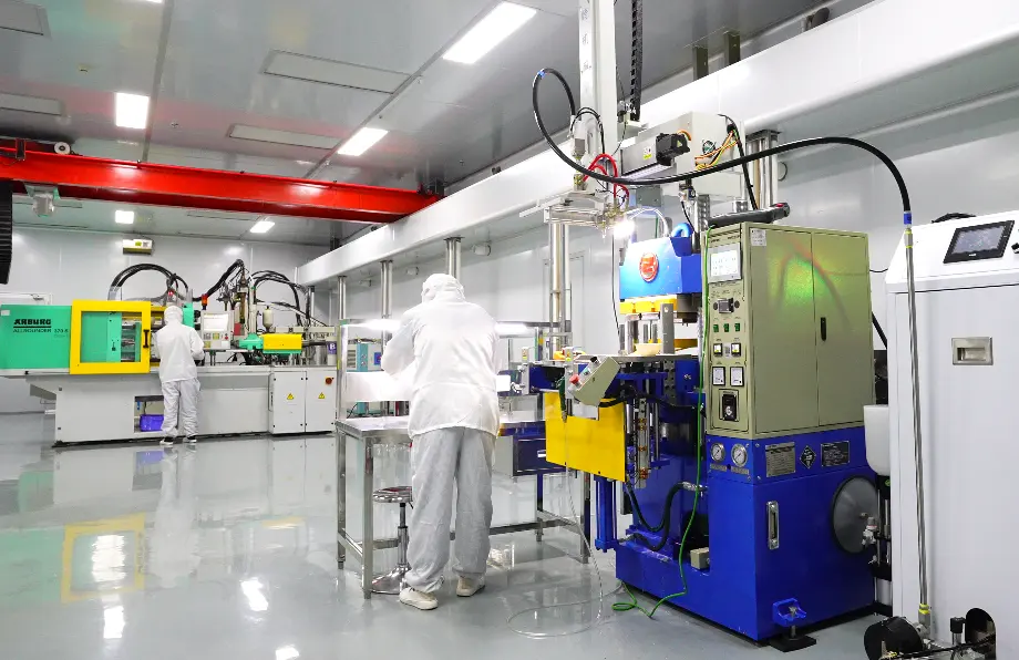
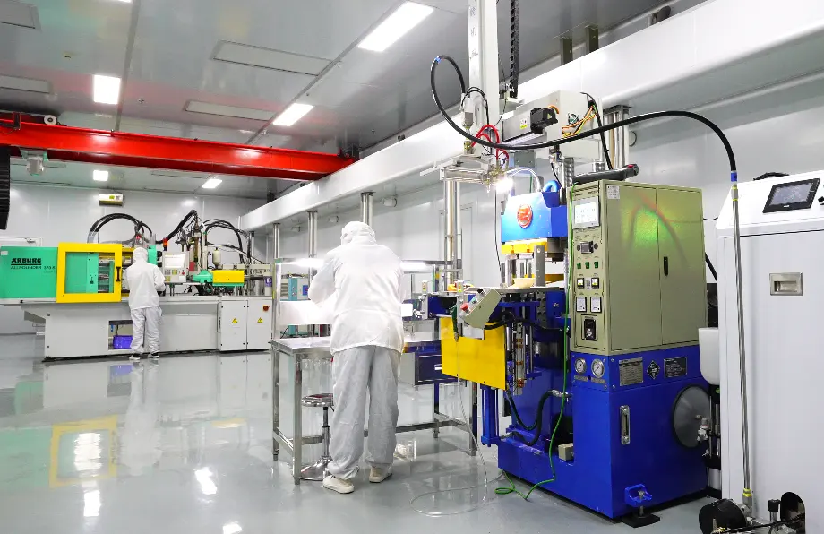
For integrated development and production, see our custom LSR mold design and liquid silicone injection molding services.
3. Control Micro Seal Geometry and Wall Thickness
Micro LSR seals often combine small dimensions with flexible lips, narrow grooves, and thin sections. These features can complicate filling, demolding, and control of excess material.
3.1 Avoid Unnecessary Thin Sections
Thin sections can increase flow resistance and make complete filling more sensitive to material temperature, gate location, and injection conditions.
However, simply increasing wall thickness is not always the correct solution. A seal's compression behavior, flexibility, contact pressure, and installation space may depend on its original dimensions.
Instead, review whether the geometry can be simplified without compromising the sealing function.
3.2 Minimize Abrupt Geometry Transitions
Abrupt transitions between thick and thin sections may contribute to uneven filling and local process sensitivity.
Where product performance permits, consider smoother transitions and more consistent cross-sections. Evaluate these changes through flow analysis where appropriate and verify them during molding trials.
3.3 Define Functional Tolerances Before Tooling
Not every dimension on a micro LSR seal requires the same tolerance.
Separate dimensions into functional categories:
Critical sealing dimensions.
Assembly and retention dimensions.
Nonfunctional external dimensions.
Cosmetic features and parting line requirements.
This approach helps engineers focus tooling precision and inspection resources on dimensions that directly affect product performance.
Avoid assigning extremely tight tolerances without a functional justification. Excessively restrictive specifications can increase tooling cost, inspection burden, and manufacturing risk.
4. Optimize Venting Without Creating Flash Paths
Air trapped inside the cavity can cause incomplete filling, burn marks, surface defects, or inconsistent molding results. Venting is therefore essential, but vent design must be compatible with the low-viscosity behavior of the selected LSR.
4.1 Identify Where Air Becomes Trapped
Vents should be designed around the expected flow path rather than added randomly.
Potential locations include:
Last-to-fill regions.
Local high points where air may become trapped.
Areas behind thin ribs or complex sealing features.
Regions identified during mold-flow evaluation or molding trials.
The correct vent location depends on gate position, cavity geometry, filling behavior, and mold orientation.
4.2 Balance Air Evacuation and Flash Prevention
A vent must provide enough capacity for air to escape without allowing excessive silicone leakage.
Vent depth, width, length, surface condition, and connection to the venting system should be evaluated as a complete design.
Do not apply a universal vent-depth specification to every micro LSR mold. The appropriate dimensions depend on the material formulation, mold finish, cavity pressure, tooling design, and required flash limits.
4.3 Validate Vent Performance During Trials
Inspect the part at the last-to-fill regions and around vent locations.
If flash repeatedly appears at a vent, review the vent geometry and local mold contact. If the cavity shows incomplete filling or trapped-air defects, review vent capacity and the filling strategy before changing multiple process variables.
The objective is not to eliminate venting. It is to create a controlled path for air evacuation while preventing unwanted material escape.

5. Improve Mold Precision and Clamping Performance
Precision tooling provides the foundation for repeatable micro LSR seal production.
5.1 Control Mold Alignment and Surface Contact
Mold halves, cavity inserts, and shut-off surfaces must remain properly aligned during repeated production cycles.
Important controls include:
Precision machining and dimensional verification.
Mold alignment and guiding systems.
Consistent insert seating.
Inspection of shut-off surfaces.
Appropriate mold maintenance and cleaning procedures.
A mold that performs well during initial trials may develop flash after repeated cycles if shut-off surfaces become worn or contaminated.
5.2 Verify Clamping Force Against Actual Molding Conditions
Clamping force must be sufficient to resist the forces generated by cavity pressure over the effective projected area.
A simplified engineering relationship is:
Clamping force requirement ≈ cavity pressure × effective projected area
This is a conceptual relationship rather than a complete machine-sizing formula. Actual calculations must account for the number and layout of cavities, runner configuration, pressure distribution, machine specifications, and an appropriate engineering margin.
Insufficient clamping can contribute to mold opening and flash. However, increasing clamp force without diagnosing the problem is not a substitute for correcting poor shut-off geometry, alignment, or mold deformation.
5.3 Evaluate Cavity-to-Cavity Consistency
For multicavity tooling, compare flash occurrence and dimensions across cavities.
If only one or two cavities show recurring defects, investigate local tooling conditions, insert alignment, venting, and cavity-specific filling behavior before changing the entire production process.
6. Optimize LSR Injection Molding Parameters
Mold design and process parameters must work together. A well-designed mold can still produce flash if the molding process is unstable.
6.1 Review Injection Speed and Pressure
Injection speed and pressure influence how material fills the cavity and how pressure develops during filling.
Instead of relying on maximum injection speed or pressure, establish a controlled filling profile based on the material, gate design, cavity geometry, and machine capabilities.
When flash occurs, review pressure trends and the location of the defect. A reduction in pressure may help in some situations, but it should be tested against the risk of incomplete filling.
6.2 Control Material Temperature and Mixing
LSR is commonly supplied as two components that are metered and mixed before injection. Mixing ratio, material temperature, and handling conditions should remain within the material supplier's specifications.
Inconsistent mixing or temperature control can change processing behavior and make defect diagnosis more difficult.
For repeatable production, verify the metering and mixing system and monitor relevant material-handling conditions.
6.3 Stabilize the Curing Process
LSR curing behavior depends on the formulation and the mold's thermal conditions.
Review mold temperature, cure time, cycle consistency, and the manufacturer's processing recommendations. Changes should be evaluated for their effects on filling, cure state, demolding, and final dimensions.
Increasing mold temperature or cure time does not automatically eliminate flash. If material escapes through an open interface before curing, the underlying tooling or pressure issue must still be addressed.
6.4 Change One Variable at a Time
A disciplined troubleshooting method makes it easier to identify the actual cause.
For example, if flash appears near the parting line, first confirm the location and repeatability of the defect. Inspect the shut-off surfaces, review the molding pressure profile, and check for contamination or wear.
Then make controlled adjustments and record the results.
This method is more reliable than simultaneously changing injection speed, pressure, temperature, and curing time.
7. Use Material Selection and Process Validation to Reduce Flash
Material properties influence filling behavior and process sensitivity.
7.1 Select LSR for the Application
When comparing LSR formulations, consider:
Hardness and elastic recovery.
Viscosity and flow behavior.
Required sealing performance.
Temperature and chemical resistance.
Applicable biocompatibility or regulatory requirements.
Compatibility with the intended molding equipment.
A formulation suitable for one miniature seal may not behave identically in another geometry or mold configuration.
Material selection should therefore be coordinated with product engineering and mold development.
7.2 Validate the Complete Manufacturing System
A successful first article does not automatically demonstrate long-term process capability.
A robust validation plan should include:
Dimensional inspection of critical sealing features.
Visual inspection of parting lines and vent locations.
Functional leak or sealing tests where applicable.
Repeatability checks across cavities.
Verification of process stability over representative production runs.
Documented acceptance criteria and defect-handling procedures.
For demanding applications, statistical process control and capability studies may be appropriate once the process is stable and the measurement system is suitable.
8. Common Micro LSR Seal Design Mistakes
| Common mistake | Potential consequence | Recommended approach |
| Placing the parting line across a sealing lip | Flash may affect sealing contact | Review alternative parting line locations |
| Using oversized or poorly controlled vents | Excess silicone may escape | Validate vent geometry and placement |
| Increasing clamp force without diagnosis | Root cause may remain unresolved | Inspect shut-offs, alignment, and pressure conditions |
| Reducing injection pressure too aggressively | Incomplete filling or short shots | Optimize the filling profile through trials |
| Applying unnecessarily tight tolerances | Higher tooling and inspection costs | Specify tolerances according to function |
| Skipping DFM and mold trials | Defects may appear after tooling is completed | Conduct early design reviews and structured validation |
9. Flash Prevention Checklist for Production
Before releasing a micro LSR seal design for mass production, review the following items.
Product design
Confirm critical sealing dimensions and functional tolerances.
Review thin lips, grooves, and abrupt geometry transitions.
Evaluate the parting line against functional surfaces.
Mold design
Verify shut-off geometry and mold alignment.
Review vent locations and dimensions.
Evaluate gate design and cavity filling.
Confirm machine compatibility and clamping requirements.
Process development
Establish a stable injection profile.
Verify material metering, mixing, and temperature conditions.
Validate curing and demolding conditions.
Document acceptable flash limits.
Quality control
Inspect critical sealing areas.
Compare results across cavities.
Conduct functional testing where required.
Establish a repeatable inspection and process-monitoring plan.
Completing this checklist before production release can reduce avoidable tooling changes and help establish a more consistent manufacturing process.
10. Frequently Asked Questions
Q1: What causes flash in micro LSR seals?
Common causes include gaps at the mold parting line, poor shut-off contact, mold misalignment, insufficient effective clamping force, unsuitable vent geometry, and unstable molding conditions. The correct solution depends on the defect location and the actual process conditions.
Q2: How can mold design prevent flash in liquid silicone rubber injection molding?
Effective measures include placing parting lines away from critical sealing surfaces, designing stable shut-off areas, controlling cavity and insert alignment, and optimizing venting. Early DFM reviews help identify risks before mold machining.
Q3: Should injection pressure be reduced to eliminate LSR molding flash?
Not necessarily. Lowering injection pressure may reduce flash in some cases, but excessive reduction can cause incomplete filling. Engineers should first identify whether the primary cause is mold clearance, venting, clamping, or the filling profile.
Q4: How do you control flash in multicavity micro LSR molds?
Inspect each cavity separately, compare defect locations, verify insert alignment, and evaluate cavity-specific venting and filling behavior. A defect limited to certain cavities may indicate a local tooling or process imbalance.
Q5: When should flash prevention be addressed during product development?
Flash prevention should be considered during initial product design and DFM, before mold manufacturing begins. Early review of sealing geometry, parting lines, venting, and tolerances can help reduce later mold modifications and production delays.
Conclusion: Prevent Flash Through Integrated LSR Design and Manufacturing
Reliable micro LSR seal flash prevention requires more than a single process adjustment. It depends on the interaction between product geometry, parting line design, mold precision, venting, clamping performance, material behavior, and process stability.
By identifying flash-sensitive areas during DFM, validating the mold through structured trials, and monitoring critical dimensions during production, manufacturers can improve quality consistency and reduce avoidable rework.
If you are developing a miniature silicone sealing ring or need to improve an existing LSR molding process, working with a supplier that integrates mold design, tooling development, and liquid silicone injection molding can help address manufacturing risks earlier.
Need support with a micro LSR seal project?
Share your 2D drawing, 3D CAD file, material requirements, annual production volume, and critical sealing tolerances with our engineering team. We can review manufacturability, identify potential flash risks, and discuss a suitable tooling and molding approach for your application.
Request an LSR mold design and injection molding quote today. Contact us