



-

Advantages of Liquid Silicone Rubber (LSR): Why It Is Replacing Traditional Rubber and Plastics
-
LSR Injection Molding (Cold Runner) vs. Compression Molding LSR (Runnerless): Process & Selection Guide
-
Medical Injection Molding DFM Checklist & Design Guidelines
-
Liquid Silicone Rubber (LSR) vs. Thermoplastic Injection Molding for Medical Devices
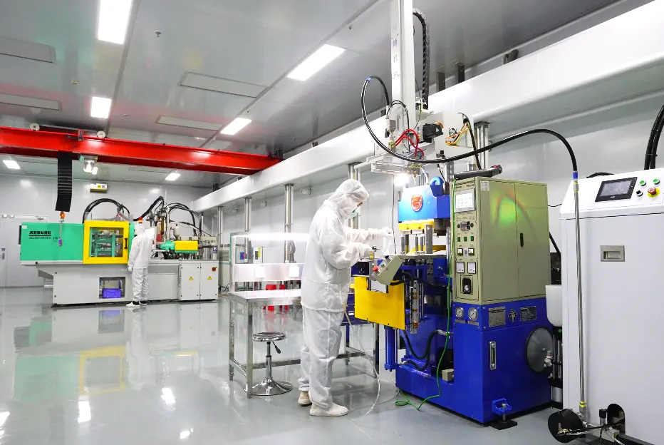
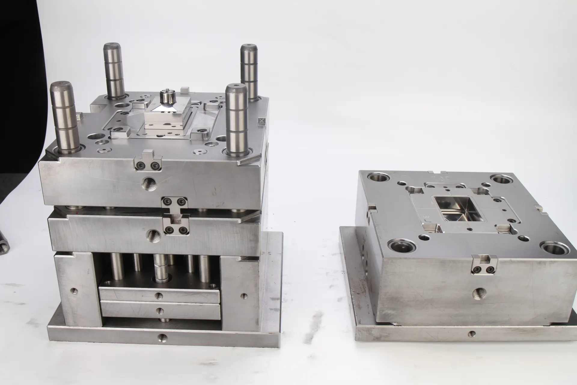
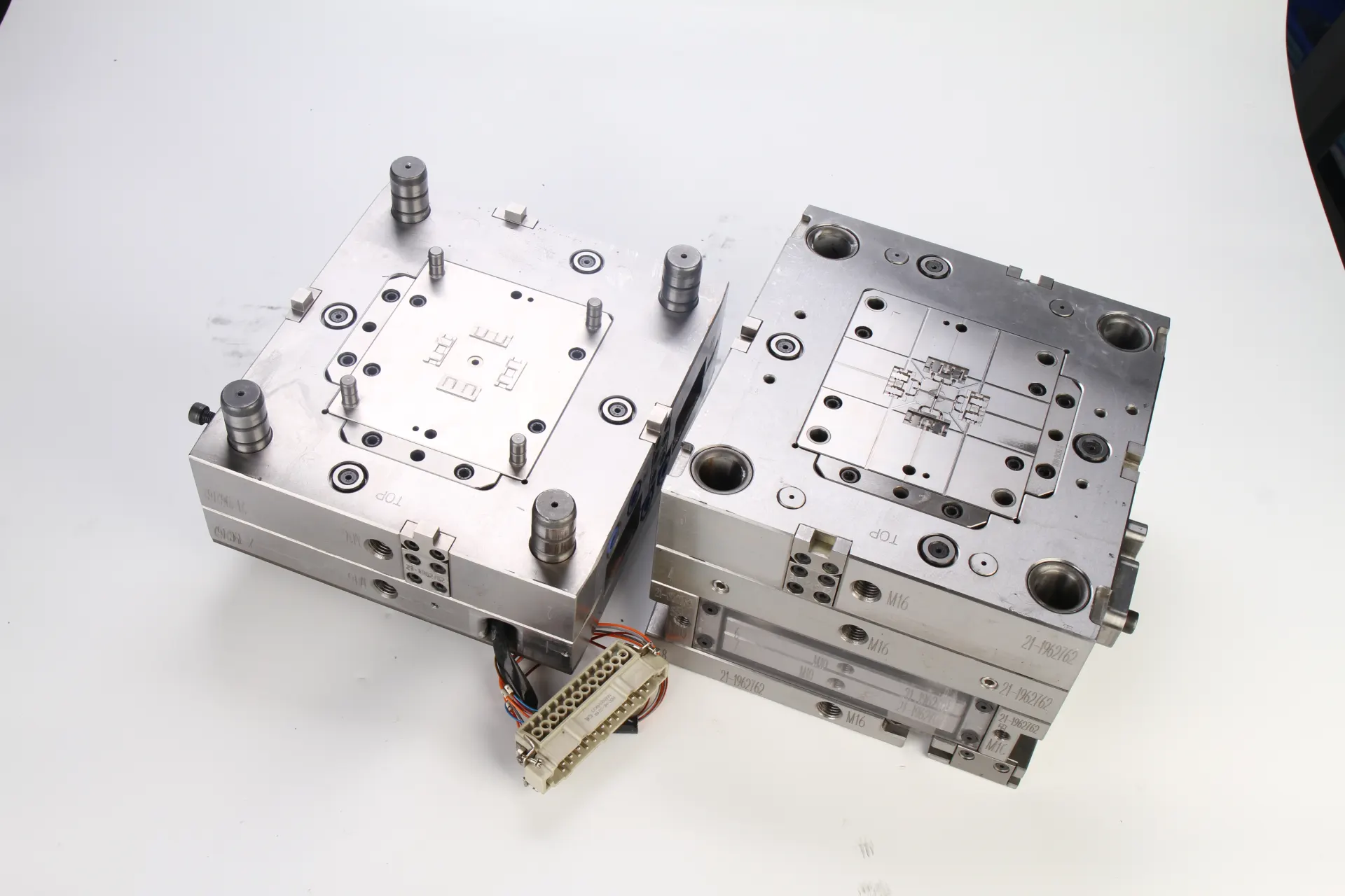

Liquid Silicone Molding Design and Tooling: A Practical Guide for Precision LSR Parts
2026-08-31




复制成功
What Is Liquid Silicone Molding Design and Tooling?
Liquid silicone rubber (LSR) is widely used for medical devices, seals, valves, wearable products, automotive components, and consumer products because of its flexibility, temperature resistance, chemical stability, and long-term durability.
However, producing high-quality LSR parts requires more than simply designing a silicone mold. Liquid silicone molding design and tooling must consider material flow, venting, parting lines, gate location, mold temperature, shrinkage, demolding, and automation.
A well-designed LSR mold can help manufacturers achieve stable dimensions, reduce flash and air traps, shorten cycle times, and improve production consistency. Poor tooling design, on the other hand, can lead to flashing, incomplete filling, dimensional variation, and difficult demolding.
For engineers and purchasing teams, understanding the relationship between LSR part design and tooling design is essential before mass production.

Key Design Considerations for LSR Molding
1. Part Geometry
LSR can be molded into complex geometries, but extremely thin sections, sharp corners, deep cavities, and uneven wall thickness can create filling and demolding challenges.
A practical design should consider:
- Uniform wall thickness
- Appropriate draft where required
- Rounded corners instead of sharp transitions
- Avoiding unnecessary undercuts
- Proper locations for seals and functional features
The earlier these factors are considered, the easier it is to develop reliable tooling.
2. Parting Line Design
The parting line determines where the two mold halves separate.
For silicone molding, poor parting-line positioning can create visible seams or excessive flash. The parting line should ideally be placed away from critical sealing or cosmetic surfaces.
3. Gate and Runner Design
LSR is normally processed through a cold-runner or other controlled material-delivery system.
Gate location affects:
- Material filling
- Air evacuation
- Weld lines
- Surface appearance
- Cycle stability
For complex parts, mold-flow analysis can help engineers evaluate the filling behavior before tooling is manufactured.
How to Design LSR Tooling
Step 1: Review the Product Design
Before mold construction, the manufacturer should review the 3D model and 2D drawings.
Key questions include:
- What LSR material and hardness will be used?
- What are the dimensional tolerances?
- Is the component medical or industrial?
- Are there cosmetic requirements?
- Does the part require automated demolding?
- Are inserts or secondary components required?
This stage helps identify potential tooling risks before production.
Step 2: Optimize the Mold Structure
A precision LSR mold commonly requires careful control of:
- Cavity dimensions
- Mold alignment
- Parting surfaces
- Venting
- Gates and runners
- Ejection or demolding structure
- Cooling/heating system
For high-volume production, tooling should also be designed around automation and repeatability.
Step 3: Control Flash and Venting
One of the biggest challenges in LSR molding is flash.
Because LSR has relatively low viscosity, excessive clearance at the mold interface can allow material to enter unwanted areas.
Precision machining and proper mold shut-off design are therefore critical.
At the same time, the mold needs adequate venting to allow trapped air to escape. Poor venting can cause:
- Air traps
- Short shots
- Burn marks
- Surface defects
The goal is to achieve controlled venting without creating excessive flash.
Step 4: Validate the Tooling
Before mass production, mold trials should evaluate:
- Filling performance
- Flash
- Part dimensions
- Surface quality
- Demolding performance
- Cycle time
- Material waste
For medical and other high-requirement applications, tooling validation and process qualification should be integrated into the overall manufacturing quality system.
Common Problems in Liquid Silicone Molding Tooling
| Problem | Possible Cause | Typical Solution |
| Excessive flash | Poor shut-off or mold clearance | Improve mold precision |
| Air traps | Insufficient venting | Optimize vent locations |
| Short shots | Poor material flow | Review gate and runner design |
| Dimensional variation | Shrinkage/process variation | Optimize tooling and process |
| Difficult demolding | Undercuts or poor geometry | Modify part/tool design |
| Visible parting line | Poor parting-line location | Move parting line to a less critical area |
The important point is that many LSR molding defects are tooling-related rather than simply machine-related.

Liquid Silicone Molding Design vs. Conventional Plastic Molding
Although LSR injection molding and thermoplastic injection molding use similar basic concepts, their tooling requirements are different.
| Factor | LSR Molding | Thermoplastic Injection Molding |
| Material | Liquid silicone rubber | Thermoplastic resin |
| Material viscosity | Very low | Generally higher |
| Flash control | Extremely important | Important |
| Venting | Critical | Important |
| Mold temperature | Heated mold | Usually cooled mold |
| Runner system | Often cold runner | Usually hot/cold runner |
| Demolding | Can be challenging | Generally easier |
Therefore, using a conventional plastic mold design approach for LSR tooling can create unnecessary production problems.
How to Reduce LSR Tooling Cost
The cheapest mold is not always the most economical solution.
A better approach is to optimize the total production cost, including:
- Tooling cost
- Cycle time
- Material consumption
- Scrap rate
- Maintenance
- Automation
- Expected production volume
For example, a more precise mold may have a higher initial tooling cost but reduce flash, scrap, manual trimming, and maintenance during mass production.
For high-volume LSR products, tooling reliability can have a much greater impact on total cost than the initial mold price.
FAQ
What is liquid silicone molding design and tooling?
It refers to the design of the LSR component, mold structure, gates, runners, vents, parting lines, and other tooling elements required to produce liquid silicone rubber parts.
What makes LSR tooling different from plastic injection molds?
LSR has very low viscosity and requires precise control of mold shut-offs, venting, material flow, and temperature. Flash prevention is particularly important.
How can I reduce flash in LSR molding?
Improve mold shut-off precision, control mold clearances, optimize parting lines, and ensure the mold is properly aligned and maintained.
Is LSR suitable for medical components?
Yes. LSR is widely used for various medical and healthcare components because of its flexibility, durability, temperature resistance, and suitability for demanding applications. The specific material, manufacturing environment, validation, and regulatory requirements should be selected according to the application.
When should tooling design start?
Tooling considerations should begin during product development, before finalizing the part design. Early DFM review can identify geometry, tolerance, gating, venting, and demolding issues before the mold is built.
Conclusion
Successful liquid silicone molding design and tooling starts with the product design and continues through mold engineering, material selection, process development, and validation.
The key areas to control are part geometry, parting lines, gating, venting, flash prevention, demolding, and tooling precision.
For complex or high-volume LSR components, involving an experienced molding manufacturer during the DFM stage can reduce tooling risks and improve production stability.
For companies developing medical, automotive, consumer, or precision silicone components, the right LSR tooling strategy can help achieve better quality, lower scrap rates, shorter cycles, and more consistent mass production.
Learn more about Liquid Silicone Injection Molding techniques