



-
Micro LSR Seal Design: Flash Prevention Tips for Precision Molding
-
Advantages of Liquid Silicone Rubber (LSR): Why It Is Replacing Traditional Rubber and Plastics
-
LSR Injection Molding (Cold Runner) vs. Compression Molding LSR (Runnerless): Process & Selection Guide
-
Medical Injection Molding DFM Checklist & Design Guidelines
Medical Mold Design & Injection Molding: How to Optimize Part Quality and Reduce Lead Times
2026-09-29


复制成功
In the medical device industry, getting your product to market faster without compromising quality or regulatory compliance is a constant challenge. Whether you are developing surgical instruments, diagnostic components, or wearable medical devices, the bridge between a CAD model and a production-ready component is medical mold design.
Poorly designed tooling leads to defect risks, costly re-tooling iterations, delayed launch timelines, and non-compliance with strict ISO standards.
This guide breaks down key Design for Manufacturability (DFM) strategies, tool engineering best practices, and quality validation workflows that optimize part quality and significantly reduce lead times for medical injection molding projects.
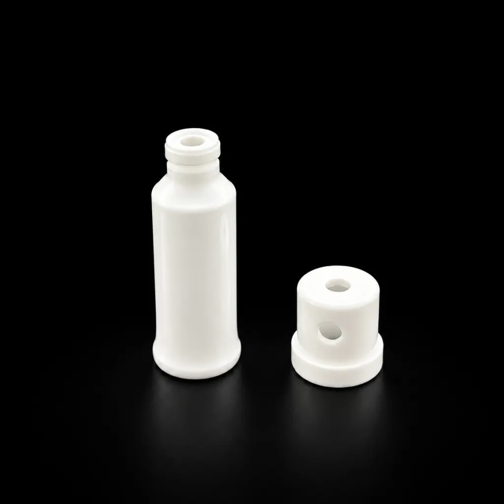
1. Implement Front-Loaded DFM to Avoid Costly Re-Tooling
The most effective way to shorten lead times is to eliminate design errors before cutting steel. Conducting a thorough Design for Manufacturability (DFM) review during the early engineering phase prevents 80% of common injection molding defects.
Key DFM considerations for medical parts include:
Uniform Wall Thickness: Inconsistent wall thickness causes differential cooling, leading to sink marks, internal voids, and structural warp. Maintaining uniform walls (or using gradual transitions) ensures dimensional stability across tight-tolerance components.
Optimal Draft Angles: Medical device housings and components often require smooth surfaces or specific textures. Providing a minimum draft angle of 1° to 2° prevents drag marks and ejection stress during cleanroom automated handling.
Strategic Gate Placement: Placing gates in non-critical cosmetic areas avoids gate vestige issues while ensuring balanced material flow into thin-walled sections.
2. Leverage Moldflow Analysis to Predict and Prevent Defects
Iterative T1/T2 mold trials can add weeks or months to your project timeline. Advanced Moldflow analysis (CAE) simulates the injection process in a virtual environment to identify potential manufacturing bottlenecks early.
With Moldflow simulation, engineers can analyze:
Fill & Pack Behavior: Spot potential short shots or air traps before tool steel is machined.
Weld Line Location: Move structural weld lines away from high-stress areas, critical for load-bearing surgical instruments.
Warpage & Shrinkage Prediction: Optimize cooling parameters and gate size to meet micro-level tolerances (down to ±0.005mm).
By eliminating guess-work during mold manufacturing, simulation reduces physical mold modifications from 4-5 iterations down to 1 or 2 trials, saving 2 to 3 weeks of total lead time.
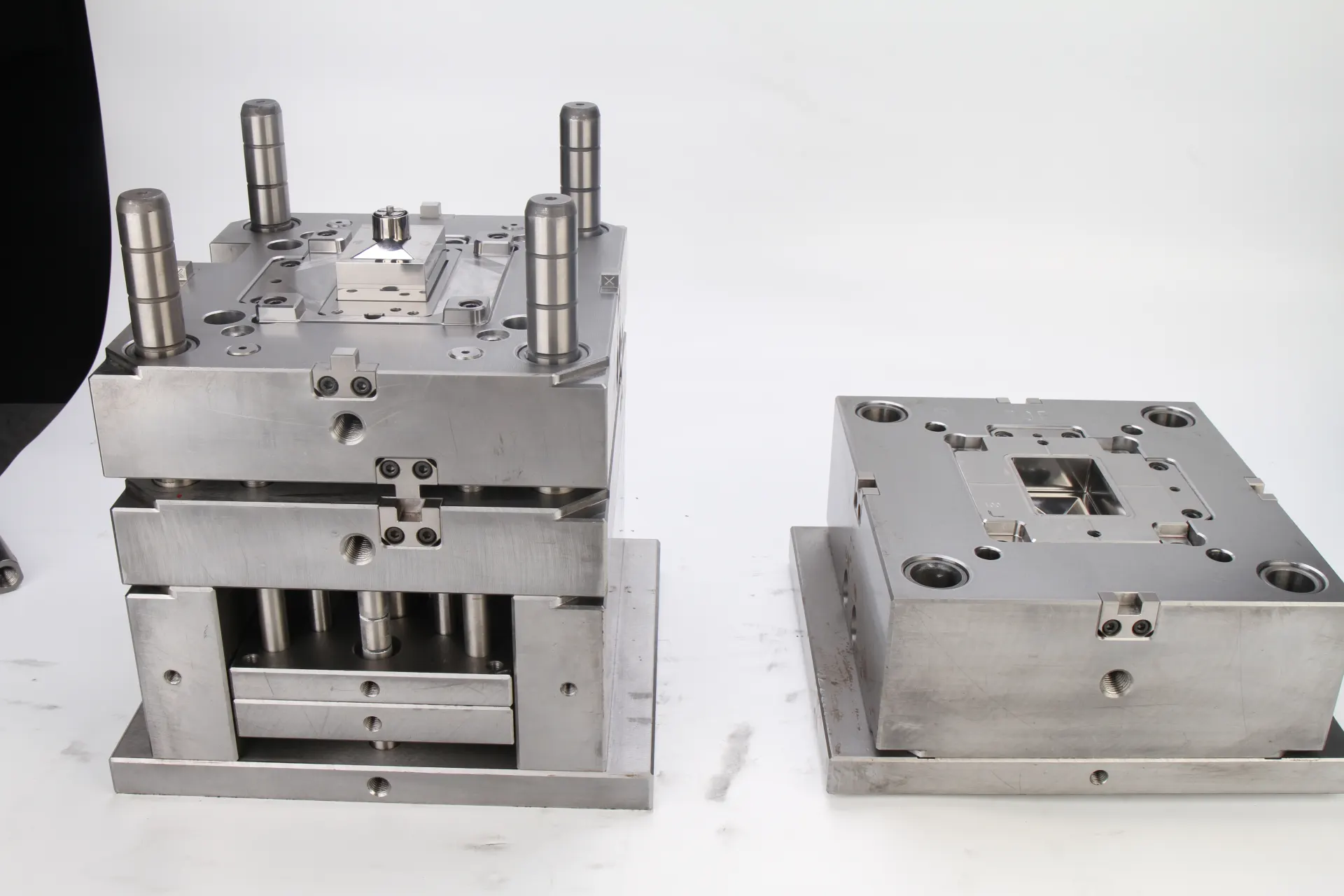
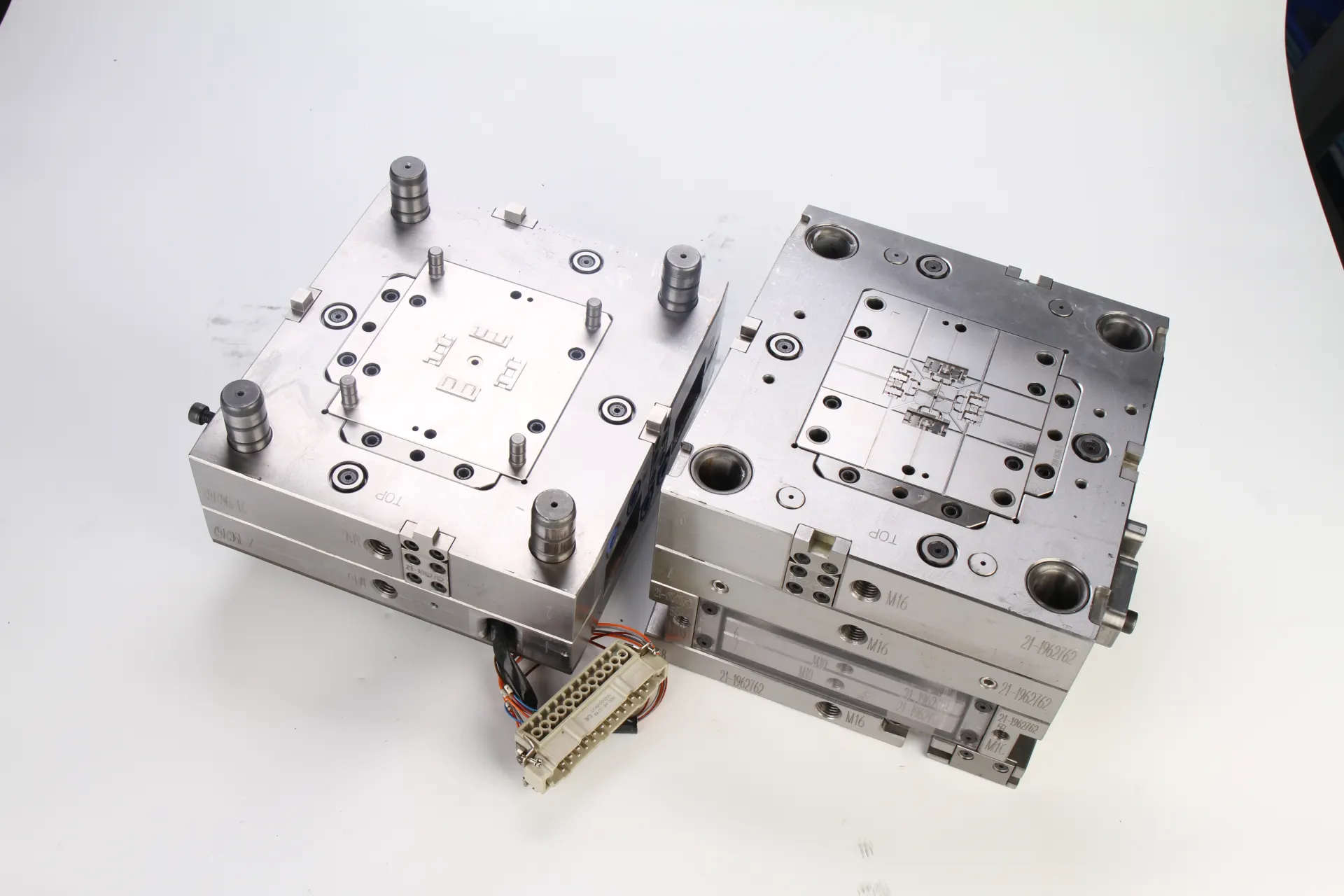
3. Advanced Tooling Engineering: Conformal Cooling & Hot Runners
Cycle time directly impacts manufacturing cost and throughput. Optimizing mold structure design helps maximize production efficiency without sacrificing part integrity.
Conformal Cooling Channels
Traditional straight-drilled cooling lines cannot reach complex geometries evenly, leading to hot spots and slow cycle times. Using 3D-printed metal inserts with conformal cooling channels allows coolant to follow the exact contours of the part.
Result: Reduces cooling times by 20% to 40% while minimizing thermal warpage in high-precision medical components.
High-Performance Runner Systems
For expensive medical-grade resins like PEEK, PPSU, or Polycarbonate, hot runner systems eliminate runner scrap, improve melt uniformity, and maintain stable pressure distribution inside multi-cavity tools.
4. Strict ISO 13485 Quality & Cleanroom Mold Validation
Speed means nothing if the molded parts fail regulatory compliance. Medical injection molding requires a rigorous validation framework to ensure every production lot meets exact specifications.
IQ / OQ / PQ Protocol Validation
To guarantee part repeatability across millions of cycles, the mold design must support standardized validation protocols:
Installation Qualification (IQ): Confirms all equipment and tooling meet design specs.
Operational Qualification (OQ): Establishes stable processing windows (pressure, temperature, speed).
Performance Qualification (PQ): Verifies long-term process stability under full production runs.
ISO Class 7 Cleanroom Standards
Medical-grade molds must be engineered for grease-free operation and particulate control to operate seamlessly inside ISO Class 7 cleanroom environments. Automated parting-line ejection and nickel-plated mold bases prevent contamination throughout the molding cycle.
Case Study: Reducing Tooling Lead Time by 35% for a Surgical Instrument Component
The Challenge: A medical device OEM needed a custom, multi-cavity mold for a high-precision surgical handle. The target lead time was compressed to 5 weeks to meet an upcoming clinical trial deadline.
The Solution: Our engineering team executed a 24-hour DFM analysis, implemented 3D-printed conformal cooling inserts, and ran full Moldflow filling simulations.
The Result:
The tool passed T1 sampling on the first attempt with zero air traps.
Cycle time was reduced by 28%.
The mold passed IQ/OQ/PQ validation 10 days ahead of schedule.
Partner with an ISO 13485 Certified Medical Molding Expert
Optimizing medical mold design is the single most effective lever for reducing time-to-market, cutting scrap rates, and securing stable long-term mass production.
Looking to optimize your medical device design or need a fast, technical DFM review for an upcoming tooling project?
👉 Request a Free DFM & Engineering Quote
Contact Information:
Email: Yuliya.chen@yizemould.com
Telephone/WhatsApp: +86 13342659272